One of the main stay motors of model rocketeers is the Aerotech G64 White Lighting engine. It is an RMS (Reloadable Motor System) engine meaning you buy the contents of the motor as a kit and assemble it in an aluminum casing. The contents are burnt up after flight. You throw that stuff out, clean the casing and you are ready to build and fly another motor. The pictures below show how an AT G64-7 is assembled. The "7" means there is a 7 second delay after motor burn out before the ejection charge is fired. This allows the rocket to slow down before ejecting the chute. IN REAL LIFE, ALWAYS READ THE DIRECTIONS THAT AEROTECH SUPPLIES WITH THE MOTOR!!
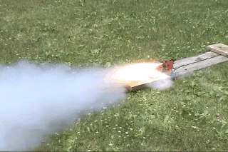
On my ROCKET VIDEOS page you can see the actual video of this motor being fired!!
 |
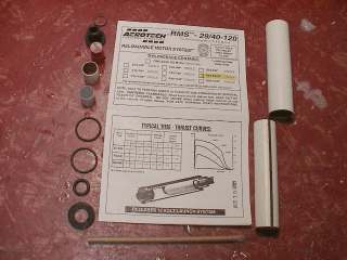 |
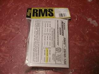
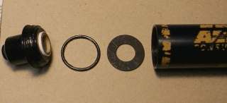
| When you buy the AT G64-7 White Lighting, you get a bag of parts like this. | The G64 is a typical RMS engine containing "O" rings, delay element, spacer, ejection charge, forward insulator, igniter, instructions and propellant grain. |
 |
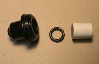 |
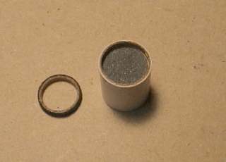
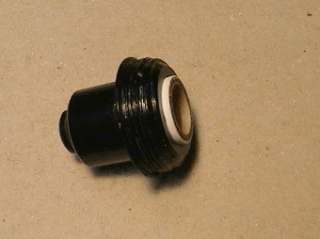
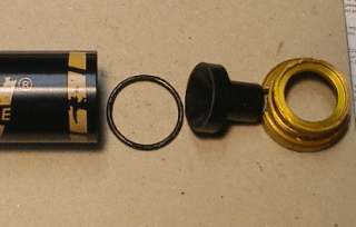
| Here the delay element is insert into its tube. To the left of it is the delay spacer which goes in the top of the tube keeping everything in place. When placed in the forward closure, the end of the tube with the spacer goes toward the grain (facing down). Don't get grease on the delay element. | The forward closure of the casing, "O" ring and delay assembly. The threads of the closures and all "O" rings are greased to allow good sealing and quick disassembly. The "O" ring goes in first then the delay assembly into the forward closure. Be careful, you do NOT want to get any grease on the delay element itself. You can use the silicon lube sold by Radio Shack for the grease. Also, check the small hole at the top of the forward closure to make sure it is clear. If it is blocked with grease or dirt, the delay element can't fire the ejection charge and you will have a lawn dart. Trust me. I know. |
 |
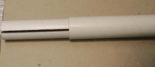 |
| What it should look like before screwing it into the casing. | Next the propellant grain tube is inserted into the liner tube. |
 |
 |
| To ease removal of the contents after firing, lightly grease the inside of the casing before inserting the grain/liner. The liner is then inserted midway between the ends of the casing. If you use too much grease, it will come out the other end and enter the delay assembly tube causing big problems! | At the forward end of the casing, the flat insulating washer is inserted, then a greased "O" ring and then the forward closure is threaded on. |
 |
 |
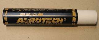
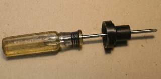
| The nozzle very often is plugged with plastic flashing which needs to be removed with a pointed object. | At the casing's aft end, the nozzle is put in place and then the last "O" ring and the aft (gold) closure is screwed in. |
 |
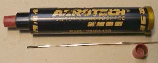 |
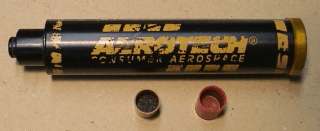
| Almost ready to use. The last step is to put on the forward end the ejection charge which is in the left red cap. The right cap is used to hold the igniter in place. Masking tape can also be used. | The completely assembled G64-7 motor with igniter. Never, ever ship or transport a motor with the igniter in place. |
|
|
The motor being fired on the ground
under a controlled experiment. |
|