 |
 |
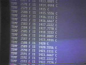
| Shot of the computer's screen. Once wired, I fired
up the 8052 computer and ran a quick little program to test the computer (BASIC program
that converts F to C). |
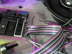
Ribbon cable connecting the computer board to the
controller board. |
 |
 |
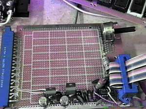
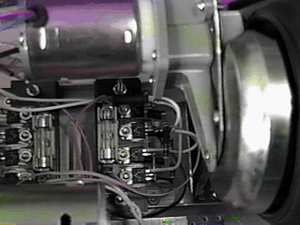
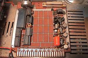
| The controller board with the motor control
transistors. |
Close up view showing the six transistors for the 2
motors. |
 |
 |
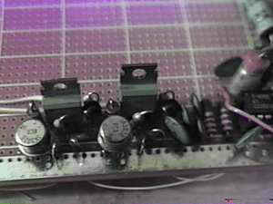
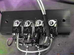
| The motor controller power transistors. There are 4
for each motor. They form a bridge and eliminate the need for a relay to switch
directions. |
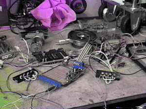
The circuit "all over the place" during
the bread board stage. |
 |
 |
| You can see the 2 sets of 4 power transistors for
the motors as well as the fuses. |
Bottom view showing the control board location and
edge connector with the motors running. |
 |
 |
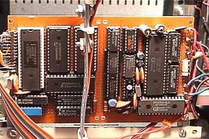
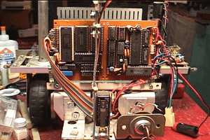
| Finished 8052 CPU board with other circuitry. |
Next an 8255 was added to the controller board to
help control the sonar unit and bumper detection. Notice that a DB25 connector is also
needed besides the board edge connector. |
 |
 |
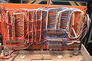
| The finished wiring of the CPU board. Over a 100'
of wire is here. |
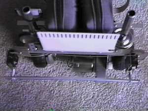
Top view looking down showing the space between the
CPU board and battery pack. |
 |
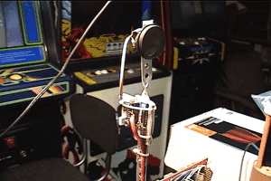 |
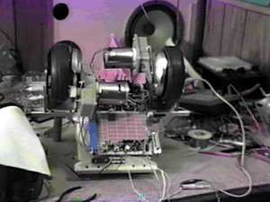
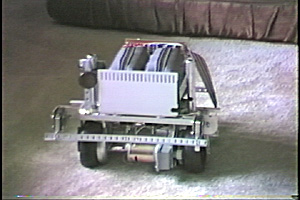
| The CPU board is mounted vertically at the end of
the chassis, behind the battery pack. |
The sonar unit is mounted above to shoot over the
front of the robot. |
 |
 |
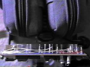
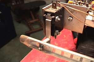
| Close up view of one of the bumper switches. |
Looking down at the front showing the front bumper
after it has run into a few things. |
 |
| See a short video of one of the first test runs of
Mikey's sonar circuit. |